Industrial Motor Control: Where Electrical Theory Meets Real Applications
Industrial electricity is one of the most fascinating fields of electrical engineering.
Behind almost every industrial production line, water pumping station, ventilation system, and manufacturing machine, there are electrical motors performing essential tasks.
But controlling an industrial motor involves much more than connecting three phases to a motor.
Engineers and technicians must understand electrical power circuits, control logic, switching devices, protection mechanisms, and operating sequences.
This is why motor control circuits are among the most important subjects in industrial electrical training.
And there is a much more interesting way to learn them: simulation.
1. Understanding the Two Main Parts of an Industrial Motor Circuit
Before exploring motor control diagrams, it's important to understand the difference between the power circuit and the control circuit.
The Power Circuit
The power circuit carries the electrical energy required to operate the motor.
In a typical three-phase direct-on-line (DOL) motor starter, it includes:
- Three-phase electrical supply.
- Circuit breaker or protective switching device.
- Main contactor contacts.
- Thermal overload protection.
- Three-phase induction motor.
The power circuit is responsible for supplying the motor with the required electrical energy.
The Control Circuit
The control circuit manages the motor's operating commands.
It commonly includes:
- START push button.
- STOP push button.
- Contactor coil.
- Auxiliary contacts.
- Overload relay auxiliary contact.
- Control power supply.
The control circuit determines when the contactor should energize or de-energize.
Understanding the relationship between these two circuits is fundamental to industrial electrical engineering.
2. How Does a Direct-On-Line Motor Starter Work?
The Direct-On-Line starter, commonly called DOL, is one of the simplest and most widely studied motor starting arrangements.
Its operating principle is straightforward.
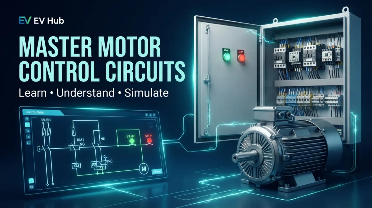
When the operator presses START, the contactor coil receives power through the control circuit.
The contactor then closes its main contacts, allowing three-phase power to reach the motor.
An auxiliary normally open contact provides a holding path, keeping the contactor energized after the START button is released.
When STOP is pressed, the control circuit opens, the contactor de-energizes, and the motor stops.
If the overload relay trips, its normally closed auxiliary contact opens the control circuit, causing the contactor to release.
This simple sequence introduces several important electrical concepts:
- Normally open (NO) contacts.
- Normally closed (NC) contacts.
- Electromagnetic contactors.
- Self-holding circuits.
- Electrical protection.
- Control logic.
3. Essential Components You Need to Understand
Magnetic Contactor
The contactor uses an electromagnetic coil to operate its switching contacts.
It is commonly used to control motors and other electrical loads.
Overload Relay
This protective device detects motor overload conditions and initiates a trip according to its characteristics and settings.
Circuit Breaker
Circuit breakers provide protection against specified electrical fault conditions, such as short circuits and, depending on the device, overloads.
Auxiliary Contacts
Auxiliary contacts are essential for creating control functions such as holding circuits and electrical interlocking.
Push Buttons
START and STOP push buttons provide manual control commands to the electrical system.
Understanding each component individually makes complex electrical diagrams much easier to read.
4. Go Beyond Theory with Control Circuit Studio
One of the biggest challenges in electrical education is moving from understanding a schematic to understanding how the complete circuit behaves.
You might know what a contactor does, recognize an overload relay, and understand the difference between NO and NC contacts.
But can you understand how all these components interact in a complete motor control system?
That's where practical simulation becomes useful.
Control Circuit Studio is a free online electrical control circuit simulator available directly in your browser.
It provides an opportunity to explore motor control concepts through circuit simulation rather than relying exclusively on static electrical diagrams.
For students, beginners, and electrical technicians, this is a practical way to complement theoretical learning.
Open the Simulator
Start exploring industrial motor control circuits with Control Circuit Studio:
Launch Control Circuit Studio – Free Electrical Circuit Simulator
5. Five Industrial Motor Control Topics Worth Exploring
If you're developing your industrial electricity skills, these are excellent subjects to study:
- Direct-On-Line (DOL) Starting: Understand the basic operation of a three-phase motor starter.
- Self-Holding Circuits: Learn how auxiliary contacts maintain a contactor's energized state.
- Forward and Reverse Motor Control: Understand how reversing the phase sequence changes the direction of a three-phase induction motor.
- Electrical Interlocking: Study how control circuits prevent incompatible commands from operating simultaneously.
- Star-Delta Motor Starting: Understand the operating sequence and the relationship between star and delta motor connections.
These topics provide a strong foundation for more advanced industrial automation and electrical maintenance studies.
6. Who Can Benefit from Electrical Circuit Simulation?
An online motor control simulator can complement learning for several audiences:
- Electrical engineering students.
- Industrial electricity beginners.
- Electrical maintenance technicians.
- Industrial automation learners.
- Technical training instructors.
- Engineers reviewing motor control fundamentals.
Simulation does not replace practical electrical training or real-world measurements, but it can make abstract electrical concepts easier to understand.
Final Thoughts: Learn Electrical Engineering by Exploring Circuits
Electrical engineering becomes much easier when theory is connected to practical examples.
Rather than memorizing the function of every electrical component, take the time to understand how they work together.
Study the diagrams, follow the control sequence, explore different motor starting arrangements, and use simulation to reinforce your knowledge.
Ready to take your industrial electricity learning further?
Try Control Circuit Studio for free and explore the world of industrial motor control circuits.
For more electrical engineering lessons, fundamentals, and practical industrial electricity resources, explore EV Hub.